Server Deployment Models
Most data centers are deployed according to two design philosophies: end of row (EoR) and top of rack (ToR). These two models impact the cost of cabling, the number of switches required, the power and cooling strategy, and the sizing of the data center facility. With the introduction of Cisco FEX, a new FEX deployment model came into existence, which uses the benefits of both EoR and ToR models.
End-of-Row (EoR) Deployment Model
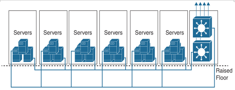
This topology consists of large, director-class switching devices at the end of each row of servers. End-of-the-row topologies require significant cabling bulk to be carried from all server racks to the network rack. The main advantage of end-of-the-row topologies is the fact that fewer configuration points (switches) control a large number of server ports.
Figure 2-9 illustrates a typical EoR deployment model.

Figure 2-9 End-of-Row Deployment Model
EoR benefits include the following:
- Fewer configuration and management points in the network
- Fewer devices, so less power required
- Lower CapEx and OpEx
- Ease in rolling out services and software upgrades
- Feature consistency (security, QoS, multicast, and so on)
- High-density server aggregation allowed at access layer
- Greater control on oversubscription
However, the EoR deployment model has the following disadvantages:
- An expensive, bulky, rigid, copper cabling infrastructure with increased cable complexity is required.
- Additional infrastructure is required for patching and cable management.
- Long twisted-pair copper cabling limits the adoption of lower-power higher-speed server I/O.
- Less flexible “per row” architecture. Platform upgrades/changes affect entire row.
- Addition of racks is limited by aggregation switch capacity.
Top-of-Rack (ToR) Deployment Model
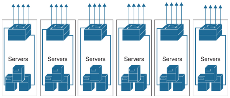
This topology consists of one-rack unit (1RU) or 2RU devices at the top or bottom of each server rack, providing server (or blade server) connectivity within each rack that’s aggregated by a switch at the aggregation layer. ToR topologies are more efficient in terms of cabling because fewer cables are required from each rack to the EoR switch. On the other hand, ToR topologies require more switches than EoR topologies require for the same number of switch ports, which increases the management burden.
Figure 2-10 illustrates a typical ToR deployment model.

Figure 2-10 Top-of-Rack Deployment Model
ToR benefits include the following:
- Flexible and scalable POD design
- Ease in replication of racks
- Shorter server-to-access switch cabling
- Fewer across-rack cables
- Lower cabling costs
However, the ToR deployment model has the following disadvantages:
- More switches to manage. More ports are required in the aggregation switches.
- ToR switches may be underutilized, resulting in unnecessary power usage and increased cooling without direct benefit to performance.
- Potential scalability concerns (STP logical ports, aggregation switch capacity).
- If the ToR switch fails, the entire rack goes offline.
- More Layer 2 server-to-server traffic in the aggregation.
- More STP instances to manage as racks are connected at Layer 2.
- Unique control plane per switch. Higher skill set needed for switch replacement.
FEX Deployment Model
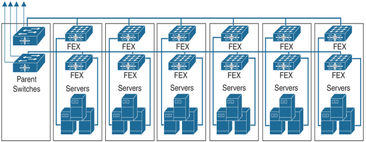
The FEX deployment model enables physical topologies with the flexibility and benefits of both ToR and EoR deployments. It uses the pod approach of a ToR deployment and the management simplicity of the EoR deployment model. Pods are retained, but they are connected into a single management domain. Together, the Cisco Nexus 2000 Series fabric extenders and the parent Cisco Nexus switch (such as a Cisco Nexus 9000 or 7000 Series switch) form a distributed modular system. The distributed modular system forms one network component from the parent switch at the EoR to the FEX at the ToR. One single point of management and policy enforcement using upstream Cisco Nexus switches eases the commissioning and decommissioning of server racks through zero-touch installation and automatic configuration of fabric extenders.
Figure 2-11 illustrates a typical FEX deployment model.

Figure 2-11 FEX Deployment Model
The FEX deployment model benefits include the following:
- Combines the benefits of both ToR and EoR architectures: high-density server aggregation switch that physically resides on the top of each rack but logically acts like an end-of-row access switch
- Reduces management devices
- Ensures feature consistency across hundreds of servers
- Reduces cable runs
- Reduces management point
- Lower total cost of ownership (TCO)


